Replacing the starter relay and the ignition lock (Ignition switch and steering lock)
Print-ready PDF export — generated on 07/10/2026
Tools
Allen key, Torque wrench, 10-piece socket set
Illustrated tools
After reassembly, check that the switch is functioning properly, that the column is locked, and that the steering wheel rotates freely. A Ignition switch and steering lock ordered without the vehicle's key code may be shipped with a separate set of keys and a different key head.
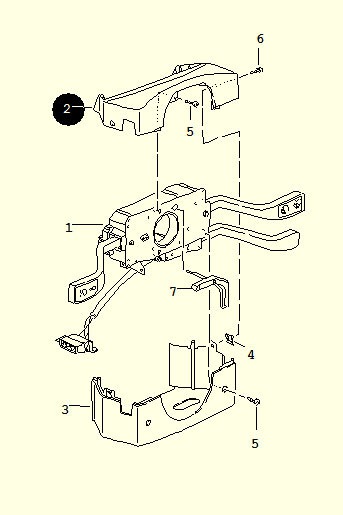
Steps 1 through 5
1.Start by disconnecting the battery.
2.Remove the steering wheel by first taking off its center section, which is simply snapped into place.
3.Use a 23-mm socket with an extension, then unscrew the center nut.
4.Remove the steering wheel by pulling it toward you.
5.Remove the five screws that hold the two half-shells in place around the switches.
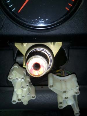
Steps 6 through 10
6.Loosen the 10-mm nut located under the switch panel.
7.Remove the circlip on the steering column, which prevents the switch panel from moving forward.
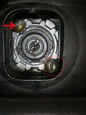
8.Unplug the two connectors located on the back of the circuit board.
9.Remove the switch plate by pulling it toward you.
10.Remove the heating and air conditioning control panel by inserting, for example, the shanks of four pop rivets into the four holes located at the corners. This action releases the tabs, similar to the installation of a car stereo. Next, pull the assembly toward you and disconnect the two connectors on the back of the unit.
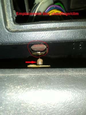
Steps 11 through 12
11.Unscrew the 10-mm nut located in the heating/air conditioning unit compartment on the right side, perpendicular to the front panel, to partially release the leather trim strip. At the other end of the trim strip, under the door-side ventilation grille, also unscrew the Parker screw.
12.Once it is released, rotate the leather strap backward for easier access.
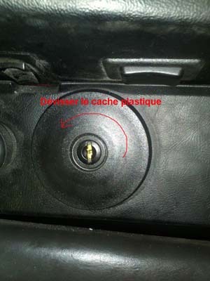
Step 1
13.Unscrew the black plastic cover around the Ignition switch and steering lock.
Steps 14 through 18
14.Get a Dremel-type rotary tool — a small, cordless drill that can accommodate various attachments — and attach a small metal-cutting disc to the chuck.
15.The Ignition switch and steering lock comes standard with self-breaking screws, of which only a domed head — without a slot — remains visible. The goal is to recreate a slot on each screw so that it can be unscrewed with a screwdriver.
16.If the screw won't come out, gradually drill into its head using drill bits of increasing diameters until it is completely destroyed.
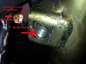
17.Here’s the trickiest part: follow the same procedure for the screw located under the steering column. The assembly consists of two parts: a threaded sleeve, which also serves as a spacer, and a self-breaking screw. Sometimes, after making the slot, the screw cannot be completely unscrewed because the sleeve and the screw rotate together in their housing.
18.In this case — which does not always occur — drill through this assembly as well so that you can remove both parts.
Steps 19 through 21
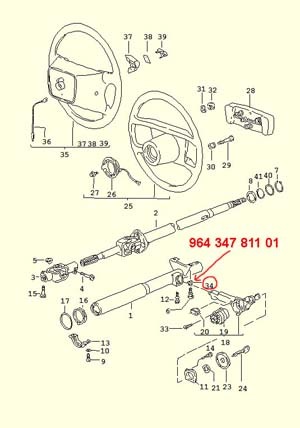
19.If you had to do this, be sure to order the threaded sleeve, part number 964 347 811 01, for reassembly.
20.You can now pull the Ignition switch and steering lock out from the left, while applying pressure toward the back. Then disconnect the main connector located behind the lock cylinder, as well as the small connector on the arm that secures the steering column.
21.To reassemble, start by inserting the threaded sleeve into its hole, taking care to insert it from the inside. The flanged end of the sleeve acts as a spacer between the Ignition switch and steering lock arm and the mounting screw.
Steps 22 through 27
22.To ensure that the sleeve fits completely into the hole, use, for example, an 8-mm Allen screw and tighten it all the way. The pressure exerted will secure the sleeve in place.
23.Reconnect the two connectors to the Ignition switch and steering lock, then insert it into its slot.
24.If the end of the arm, with its milled section, does not fit, lightly file down the flat part to reduce its height.
25.When returning the vehicle to service, install the specified shear bolt — part number 901 347 753 00, subject to confirmation by the VIN — to maintain the original anti-theft function. A standard bolt should only be used for temporary installation in a workshop.
26.To secure the barrel, use the specified screws — part number 999 219 017 02, subject to confirmation — and follow the manufacturer's recommended tightening procedure.
27.For the rest of the reassembly, follow the disassembly steps in reverse order; there are no particular difficulties to note.
Explanation
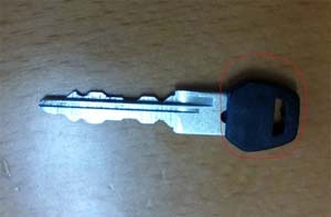
After reassembly, check that the switch is functioning properly, that the column is locked, and that the steering wheel rotates freely. A Ignition switch and steering lock ordered without the vehicle's key code may be shipped with a separate set of keys and a different key head.