

How a Vane MAF sensor Works
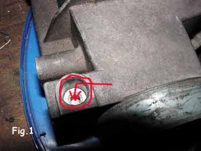
The MAF sensor provides the engine control unit with information on the amount of air intake. The reference stoichiometric ratio of approximately 14.7: 1 corresponds to one mass of air for one mass of gasoline, not to volumes. The adjustment screw must not be adjusted without following the manufacturer’s procedure, using a gas analyzer, and inspecting the fuel injection system.
Overview
The MAF sensor provides the engine control unit with information on the amount of air intake. The reference stoichiometric ratio of approximately 14.7: 1 corresponds to one mass of air for one mass of gasoline, not to volumes. The adjustment screw must not be adjusted without following the manufacturer’s procedure, using a gas analyzer, and inspecting the fuel injection system.
Explanation
A mixture that is too rich increases fuel consumption and emissions and can contaminate the oil or the cylinders. A mixture that is too lean increases the combustion temperature and can cause engine knocking or damage. The adjustment must therefore be made only using the specified instruments and values.
Explanation
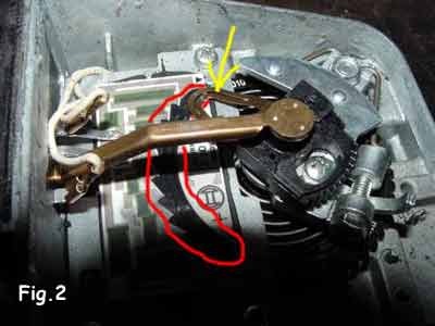
Another key function of the mass airflow sensor, in conjunction with the oxygen sensor, is to provide the engine control unit with information about the state of the fuel-air mixture so that it can apply the necessary corrections to fuel injection and ignition timing. The top view — shown in the photo above — illustrates its components. The assembly functions like a potentiometer, or an adjustable resistor. The slider, located under the yellow arrow, moves along a graphite-coated track outlined in red. This track features stepped markings corresponding to predefined values, measured in ohms.
Explanation
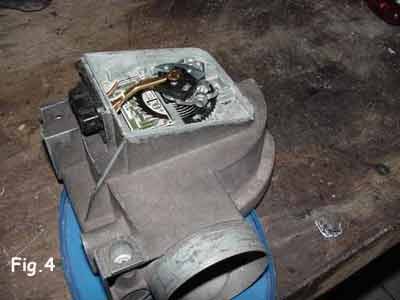
Depending on the vacuum created in the intake manifold, the flap located directly below the slider’s axis pivots around that same axis, allowing more or less air to enter. There is therefore a direct relationship between the position of the slider — and thus the value of the adjustable resistance — and the flap’s opening angle. The variable ohmic value applied to the ECU’s input produces a potential difference, or voltage, measured relative to ground — that is, the chassis ground.
This voltage is then converted into binary form — 0s and 1s — and interpreted by the computer based on other parameters, such as temperature or knock. This results in a multitude of possible combinations, much like a multidimensional data table — in other words, a kind of chart. This helps you better understand the purpose of all these measurements.
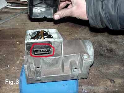
The connection port is located on the back, circled in red in the photo.