Replacing the Dual Ignition Belt
Print-ready PDF export — generated on 29/08/2026
Tools
Allen key
Illustrated tools
Caution: WARNING: Do not attempt this procedure without taking all necessary precautions. A mistake could result in engine damage. Work with a partner, and take your time. If you have any doubts about your ability to perform this task, do not attempt it; instead, have a professional perform the work.
Overview
Caution: WARNING: Do not attempt this procedure without taking all necessary precautions. A mistake could result in engine damage. Work with a partner, and take your time. If you have any doubts about your ability to perform this task, do not attempt it; instead, have a professional perform the work.
The internal belt of the dual ignition system is a key maintenance item on the affected M64 engines. The replacement interval and procedure must be confirmed in the vehicle’s documentation. If the belt breaks, it can cause the second distributor to lose synchronization, resulting in misfires or damage.
Engine Alignment
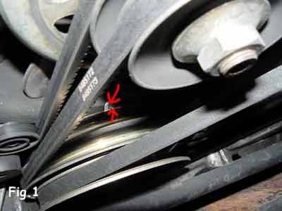
Before removal, position the engine at the specified mark and check the alignment between the crankshaft pulley and the oil pan. This position must remain unchanged throughout the procedure.
Explanation
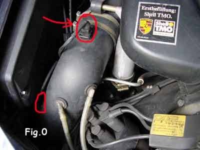
Remove the heater hose by loosening the clamp — red arrow, Figure 1 — then disconnect the two connectors circled in red in the same figure.
Explanation
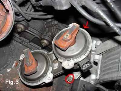
Align the two reference marks on the crankshaft pulley and the engine crankcase — Figure 4. On the distributor side, you should have the position shown in Figure 3, with the protrusion on each distributor aligned with the mark indicated by the red arrow.
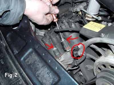
Disconnect the connector located on the front of the dual ignition module — marked with a red circle — as well as the small coolant hose located just below it. Then unscrew the four screws that secure the two distributor caps.
Loosen the nut at the base of the distributor — red circle, Figure 4 — then remove the assembly from the top by rotating it.
Explanation
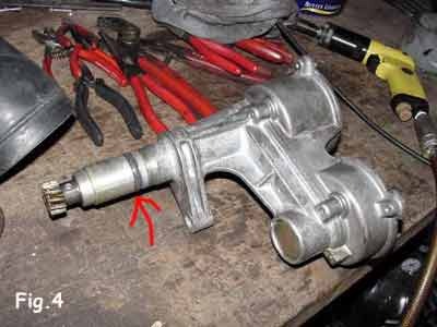
If the assembly does not come apart, the O-ring that provides the seal — red arrow, Figure 5 — has probably become stuck. Do not use a screwdriver or any other tool to pry it open: you risk deforming the aluminum body. Instead, use a strap placed underneath to apply vertical pull.
Explanation
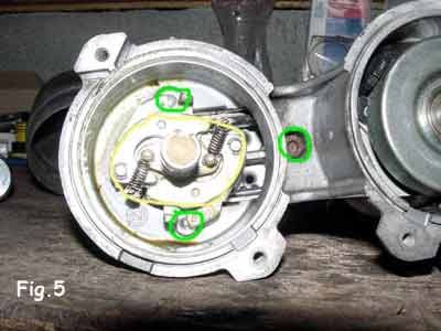
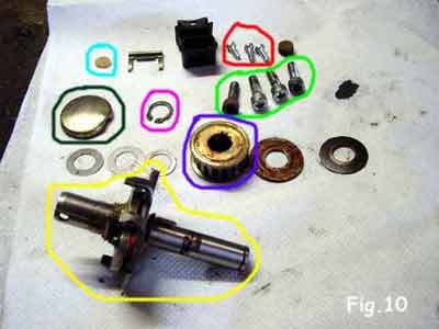
Clamp the body of the dual igniter in a vise, but do not tighten it too much, as the part is fragile. Loosen the three BTR screws — marked with green circles in Figure 6 — and then remove them.
Explanation
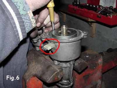
Do the same with the three Phillips-head screws on the primary housing, shown right next to them in Figures 6 and 7, then remove the connector cover to achieve the configuration shown in this figure — red circle.
Explanation
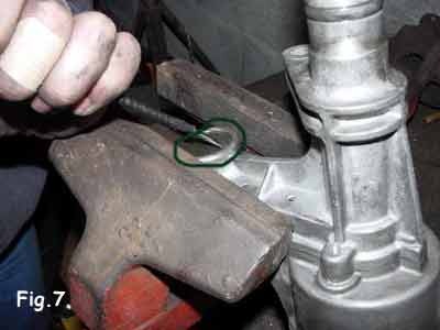
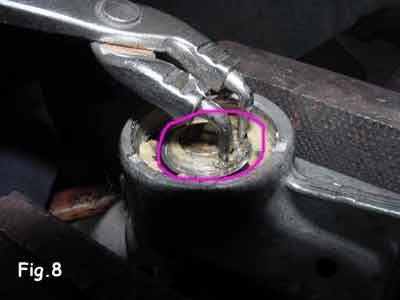
Place the double igniter housing in the vise, then remove the protective cap as shown in Figure 8 (green circle) using a screwdriver.
Explanation
Use a circlip plier to remove the circlip and release the centrifugal feed shaft — Figure 6, circled in yellow — then cut the worn belt to remove it.
Clamp the double igniter housing back into the vise.
Explanation
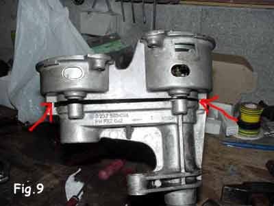
Next, begin to separate the upper part of the dual igniter from the lower part by gently tapping it with a rubber mallet until you achieve the clearance shown in Figure 10.
Explanation
Warning: The guide reduction described in the original article is not presented as a manufacturer-recommended method. Have this modification approved by a dual-ignition specialist before performing it.
The two halves are centered by two small guides located at each end — see the red arrows in Figure 10.
To install the new belt, cut off about 2 mm from the length of each guide.
Explanation
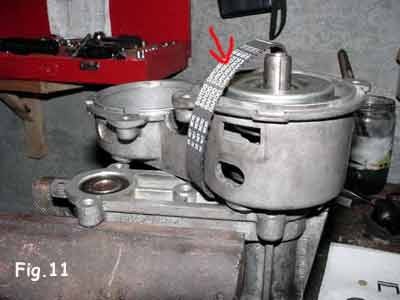
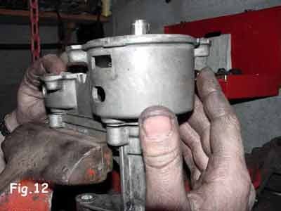
This modification allows the upper section to be rotated around a horizontal axis, and the space created in this way can be used to slide the new belt into place — see Figure 12.
Explanation
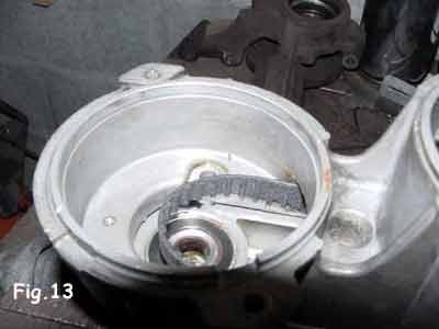
Once the belt is in place, rotate the upper section so that it aligns with the lower section. Then snap the two guides into the lower section — Figure 13 — by gently tapping them with the rubber mallet.
Installing the belt
Make sure the belt is properly engaged on the toothed pulley — without any twisting or pinching — before continuing with the reassembly.
Explanation
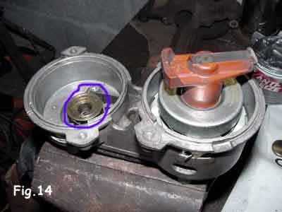
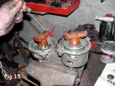
Reinstall the toothed pulley with the belt — Figures 6.14 and 6.15 — making sure to include the washers. Next, reinstall the centrifugal feed shaft after cleaning and greasing it, then tighten the three BTR screws and the three Phillips screws to secure the assembly.
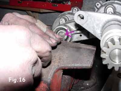
Once again, place the dual igniter housing in the vise and reinstall the circlip into its seat using pliers or a screwdriver — Figure 17. Then replace the protective cap after applying grease to it.
Checking Finger Alignment
Check the relative orientation of the two ignition fingers before closing the housings. Any misalignment can cause a misfire.
Explanation
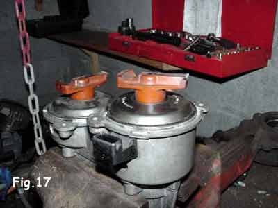
Reattach the connector cover — Figure 18 — and reinstall the ignition fingers and their protective cover. Finally, reinstall the assembly into its housing, making sure the alignment marks are still aligned with the crankshaft pulley and the engine crankcase.
If necessary, lightly lubricate the O-ring — Figure 5, red arrow — to make reassembly easier. Replace the retaining nut — Figure 3, circled in red — and tighten it securely. Reconnect the various connectors and the belt cooling hose. Reinstall the two Delco heads and secure them. Reinstall the heater hose and tighten its clamp. Perform a final check, turn the ignition on, and then start the engine.
Final Inspection of the Dual Igniter
The reassembled unit should rotate freely, without any resistance. Check the connector, the coolant hose, the covers, and the cable routing one last time.